Thursday, June 23, 2016

The barest fundementals

This post is written to be a pre-introduction to Arduino for an absolute novice (i.e. someone without a background in computer science, engineering, or calculus based physics).  We will discus the simplest electrical concepts that will be expanded upon as future lessons progress.

The water in pipes analogy

Imagine a water tower with a water wheel at the base, piping between the tank and the water wheel, and a valve to allow or stop flow.

Let's start by saying the valve is closed.

In physics, the water in the tower is said to possess 'potential energy.'  The water isn't doing anything; it is just sitting there.  But it is up high, and because of gravity it has the potential to be used below to turn the water wheel.


Now suppose we open the valve.

When the valve is opened, the speed of the water coming down the pipe will depend on the height of the tower and the water level in the tank, as well as whether the valve is fully open or only part way.

The speed of the water flow will influence how fast the water wheel turns, and correspondingly, how much energy can be extracted from it (if, for instance it were connected to a generator, or a device used for grinding grain, or whatever one uses a water wheel for).  

Here we have already touched on the fundamentals necessary to talk about electricity.
  • Voltage is a measure of electrical potential, similar to the height of the water level.
  • Current is a measure of how much electricity is flowing, similar to the rate of water flow through the pipe.
  • Resistance is a measure of how much the wires and electrical components slow down the electrical flow (current) similar to the way the valve passes more or less water based on how open it is.

Circuits


A circuit is a loop.  Outside of the field of electronics, a race car might be said to be completing a circuit as it goes around a loop-shaped track. When talking about electrical systems, the term circuit is used to describe the path the electricity travels on when moving from a location with higher potential (voltage) to one of lower potential, and a simple diagram will show that that path is also a loop.


The circuit diagram above is for a flashlight.  A legend for the icons is bellow. 

Switch


Resistance
Light Bulb
Battery

The lines connecting the icons are the flashlight's wiring. 


Current flows on the wiring out of the positive side of the battery (marked "+"), through the switch (when the switch is closed), and through the light bulb to the negative side of the battery (marked "-").  So altogether it forms a loop or circuit.


Although in the diagram the resistance is marked as a single icon, in real life there is resistance all along the wire, inside the battery, in the switch and in the light bulb.  The resistance is marked as a single icon because it makes analysis of the circuit easier; if you want to know why, ask how in the comments, but it requires a bit of explanation that I didn't intend to get into here.

Bringing it all together

The concept of a circuit diverges from the water in pipes analogy a bit: In the water tower example, the water could just dump out on the ground after hitting the water wheel, and maybe it would run into a river or wherever.  A loop could be formed by having a collecting pool and a pump that charges water back to the tower, perhaps, but that does nothing to illustrate a fundamental difference between water and electricity: If a circuit is not connected by wire or some other current carrying material (light bulb filament, or the material from which the switch is made) the break is equivalent to an opened switch: current won't flow.  In terms of water flowing through pipes, if a pipe is severed, water will blow everywhere until a valve is closed stopping flow into the pipe upstream. 

In physical terms, a disconnected circuit experiences infinite resistance to (electrical current) flow, whereas a severed pipe presents zero resistance to (water) flow.  The implication of this is that when we are working with electricity, for anything to happen the current will need a way in (a path from high potential), and a way out (a path to low potential)


Thursday, June 9, 2016

How to make Retropie work

This post is for visitors to my family's VRBO house.

In the downstairs bedroom I've provided a RetroPie, a Raspberry Pi micro-computer configured to emulate Nintendo Entertainment System and Super Nintendo for playing each respective systems' video games.


The RetroPie is fairly straightforward to use, but these instruction may help if any problems are encountered.
  • Turn on the TV, tuned to video input and plug in the micro USB cable.
    • If nothing happens, unplug and try again, as sometimes it doesn't take on the first power up.
    • When plugged in you can see a couple LEDs shining through the vent on the side.  When it is working right the red will be illuminated, as well as the green; when it isn't working the red will be on but not green.
  • If things are going correctly, a screen with four raspberries will be displayed, followed by some computer script, a 'Retropie' splash screen, a bit more script, an 'Emmulation Station' splash screen, and finally the main interface.
    • On rare occasions a guest may be prompted to configure the controller.  Follow on-screen prompts to configure the buttons.  The 'L' and 'R' shoulder buttons should be configured to the 'bottom L' and 'bottom R' buttons, respectively.  Buttons not found on the controller can be skipped by holding down any button for a few seconds.
  • On the main interface you can use either USB controller to select Nintendo Entertainment System or Super Nintendo by pressing left or right on the controller 'D' pad, and pushing the 'A' button. You will find long lists of games you can try.  
  • If you get tired of one game while playing you can press 'start' and 'select' at the same time to exit from that game.
  • The other options probably won't be of much interest to a casual user, but if you find something you like please leave me a comment, as I haven't spent a lot of time exploring the games and such that come with the default RetroPie distribution.  I think there is Doom and Minecraft, but I haven't spent any time on them.
All Super Nintendo and Nintendo Entertainment System ROMs are legal copies of games from my collection, procured between ~1987-2005.

Fully configured devices are available for purchase on my ebay store (link), but the micro SD card that comes with it will necessarily not contain the game ROMs (we aim to avoid unlawful distribution of those files).   If the micro SD card goes missing during your stay a $20.00 replacement fee will be assessed from the credit card that was used to make the deposit for the house.  If the entire system is removed the replacement fee is $100.00.

Incidentally, this system is capable of playing games from systems as powerful as the original Playstation.  A more powerful version capable of emulating Nintendo 64 titles will be made available when the Raspberry Pi 3 becomes more available.


Wednesday, March 9, 2016

Arduino Pro Mini Clones Part 2

Continuing my investigation of cheap Chinese knock offs of Sparkfun's Arduino Pro Mini design...

As mentioned in Part 1, I purchased one of each of what I called the Common, Two Row and Big Oscillator PCB designs.  Since Part 1 I went ahead and bought the other two common designs as well, the old and new Sparkfun designs.

Of course the first difficulty a novice will find when graduating to using pro mini clones is overcoming the lack of USB port.  Anticipating this I ordered the Two Row board as a package deal that came with three different kinds of USB to Serial converters: PL2303, CH340 and CP2102.

All three converters required drivers, found at the following sites (I was using a Mac, for other OSs you may have search around):

PL2303 - http://www.prolific.com.tw/US/ShowProduct.aspx?p_id=229&pcid=41
CH340 - http://www.wch.cn/downloads.php?name=pro&proid=5
CP2102 - https://www.silabs.com/products/mcu/Pages/USBtoUARTBridgeVCPDrivers.aspx

The wiring between any converter and board should be as follows:
5V to VCC
Ground to Ground
TX to RX
RX to TX

After loading up drivers and figuring out the correct wiring, the next problem I ran into was that all three of these USB converters have no support for automated resetting of the board during programming.  This results in an error while programming almost every time (I can't say why, but on the first try the program went through perfectly without any messing with reset, but later attempts almost always failed).

I started searching for the reason and was pretty disappointed by the level of detail in the answers (basically, answers were along the line of "reset before/during upload").  One suggestion was to turn on verbose output,
which I found helpful at slowing down the upload process, but I still couldn't figure out exactly when to press reset, whether to hold it for a little while or release immediately and so forth.  After a bit of trial and error I did get the timing figured out and I will post a video of the process so that it is perfectly clear how to get a good load.  Hopefully a video can save any intrepid readers that same trial and error, as pushing and releasing the reset button has a certain rhythm to it that works for me.

Once the timing was sorted out, the converters all work fine, and now that the drivers are loaded on my computer I could grab one indiscriminately when I want to load a sketch.

Ultimately, it should be noted that this is a super scrimp-and-save approach that led to extra headaches which an FTDI USB to serial converter would avoid for just a little more money spent, as the FTDI converters support automated resetting during sketch uploading.  After having so much fun figuring out how to use the others I went ahead and purchased an FT232RL FTDI USB to serial converter.  I intend to use it as my go-to programmer, allowing upload without this rhythmic button pushing nonsense.  It didn't need any drivers, though I use a Mac and I think I heard mention of needing drivers for windows.  Good luck finding them.

Finally, I did see some suggestions to solder headers to the 6 pins of the pro mini used in uploading, and while I agree that it is good engineering practice, I don't tend to have the patience for it.  I usually can still get a good load if I hold the header with the wires to the converter in contact with the board just so.  Your mileage may vary; break out the soldering iron if you think you need it.

Wednesday, February 17, 2016

DC motor blues Part 2

Because the circuits shown in Part 1 haven't been worked on for a while, this post is to outline my plan of action for picking the project back up and troubleshooting using a systematic approach.  Part 3 will post results and code snippets.


-Build the circuit as shown in the first picture of Part 1 using most recent save of code to confirm the problem exists as documented (create a baseline).
-Build the circuit and use code from Adafruit Learn Arduino Lesson 15 (https://learn.adafruit.com/adafruit-arduino-lesson-15-dc-motor-reversing/arduino-code) to see if the motor is causing the freeze ups.


-Used the existing code with gyro but LEDs in place of the motor, in parallel with bias in opposite directions; expectation is that one LED will illuminate when tilted one way, the other for the other way.  Check that the serial output never freezes up for the duration.


-Built the circuit from the first picture of Part 1 using different DC motors.  The motor is called 1.5-3V, but it is weak at those voltages.


-Stack L293D chips, in case they are being overloaded.  Connect all grounds, as the ground pins are also described as heat sink in documentation.
-Use Arduino Uno instead of Nano as the micro controller. 
-Build the circuit as shown in the second picture of Part 1 and repeat all previous steps.


This will provide some data on whether the problem can be isolated.  Additional steps are:


-Build circuits as shown in other projects that work online, using their code.  See if the same problem occurs.
-Consider reworking code to allow using a potentiometer to control motor speed as in Lesson 15 while taking readings on the Gyro (attempt to divorce Gyro and motor)

DC motor blues Part 1

This post is to document a problem I'm having getting some electronics (that will drive a toy I'm building) to work.


The toy is a variation on a mobile inverted pendulum (see https://trandi.wordpress.com/2014/01/05/self-balancing-robot/ for inspiration). 


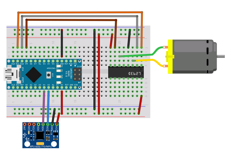
The parts list seems to be ever expanding but for now I've got an Arduino Nano (sometimes I use an Uno as well), a 7805 Power Supply, an L293D H bridge IC,  a GY 521 gyro/accelerometer combo and a 1.5-3 volt DC motor I got from RadioShack (http://www.radioshack.com/1-5-3vdc-metal-gear-motor/2730258.html), along with typical prototyping essentials (wires, resistors, capacitors, diodes, transistors and a breadboard).  I also grabbed the power supply from my playstation 2 (8.5V, 5amp DC) and another from an old modem and have been using them as the power source(s) when not powering from USB.


As preparatory work I soldered wires onto the motor and a male pin header onto the GY 521. 


For first effort I wired things up as below, powering the Nano through USB and everything else off the +5V pin on the Nano.


The code attempts to alter the speed of the motor based on the orientation of the GY521.  The problem that I encountered was that always after a few times going from stopped to speed the motor would get hung at max speed and the Arduino/Serial output would freeze.  This is a problem others have encountered (see http://forum.arduino.cc/index.php?topic=132493.0 and the comments of the trandi link above) and to my knowledge no one has solved.


The circuit above is a revised circuit based on comments on the trandi link, adding a separate 7805 power supply fed from the 8.5V Playstation AC adapter, a 5V AC adapter for the motor and powering the Arduino from USB still.  This circuit could hardly be more electrically isolated but still the motor locks up at max speed and the Arduino freezes.

This post has languished as a draft for a long time, so I will post now and add more as subsequent parts when I get back to it.


Arduino Pro Mini Clones Part 1

This post is to document my foibles learning to use Arduino Pro Mini Clones.

When I decided it was time to get away from the larger Arduino boards I started shopping for Pro Mini clones, since they can be had pretty cheaply, and can be fit into just about any application.  I discovered multiple different PCB designs and decided to buy one of each of the 3 most common unofficial designs to see if I could identify any difference.  In all cases these are 5V 16Mhz boards, as I wanted as close a match to my experience with Arduinos Uno and Nano as possible. 

Below is a summary of common Arduino Pro Mini (and clones) PCB designs:

Official designs (I didn't purchase either of these, so please take this with a proverbial grain of salt):

-Old Sparkfun Design: (https://www.sparkfun.com/products/retired/9218) sometimes these are sold a bit cheaper than the rest listed below.  If someone has a project that they want to put into large scale production, and the project doesn't happen to use the A6 and A7 pins that are not broken out on this board, I suppose the small savings in cost would add up?

 -Current Sparkfun Design:  (https://www.sparkfun.com/products/11113) this one breaks out the A6 and A7 pins.  Exact copies of this design are popular on Ebay.

Unofficial designs (these are the three designs I purchased):

-Common design:  This seems to be the most common unofficial design, so for brevity I refer to it as the 'common' design for pro mini clones.  It looks like a modification of the old Sparkfun design, but tweaked to have a smaller reset button, making room for three pins (A6, A7 and one additional ground pin) that weren't broken out in the retired Sparkfun board.  


-Two Row design:  I will refer to this as the 'two row' design, as it can be recognized by the two five-pin rows (or seven?  When I say five I am not counting the pins that are part of the long-edge rows of 12 pins each) along the button side edge for a total of 40 pins broken out.  The one I bought has those pins marked as shown.  I don't know what MIS, MO9, and SCK pins are but if they look like something you need, buy boards of this design, I guess?
-Big Oscillator design:  I refer to this as the 'big oscillator' design as it is recognizable by the large oscillator and smaller microcontroller chip on the board.  It has 34 pins. Before the boards arrived I looked at this and thought it was the stupidest looking board with the giant oscillator, but the black board and blue LED actually make me like it best aesthetically, now that I've used it a bit.  I did see boards with the Big Oscillator design on blue PCB, if anyone cares.

Besides those listed above I saw a few variations on those listed above: A Big Oscillator design but with the larger microcontroller chip and one extra pin broken out (five pins along the button side edge, rather than four, the extra pin assumed to be another ground) and a Common design with four pins next to the button rather than 3, the extra pin apparently one more VCC, but I didn't bother purchasing either.
The only conclusion I can draw about the different designs is to consider your project needs for the  pins that are or are not broken out on the board.  All boards loaded up fine once I figured out the timing for resetting and got the drivers installed for the different USB to serial converters I was using (the subject of Part 2).