Because the circuits shown in Part 1 haven't been worked on for a while, this post is to outline my plan of action for picking the project back up and troubleshooting using a systematic approach. Part 3 will post results and code snippets.
-Build the circuit as shown in the first picture of Part 1 using most recent save of code to confirm the problem exists as documented (create a baseline).
-Build the circuit and use code from Adafruit Learn Arduino Lesson 15 (https://learn.adafruit.com/adafruit-arduino-lesson-15-dc-motor-reversing/arduino-code) to see if the motor is causing the freeze ups.
-Used the existing code with gyro but LEDs in place of the motor, in parallel with bias in opposite directions; expectation is that one LED will illuminate when tilted one way, the other for the other way. Check that the serial output never freezes up for the duration.
-Built the circuit from the first picture of Part 1 using different DC motors. The motor is called 1.5-3V, but it is weak at those voltages.
-Stack L293D chips, in case they are being overloaded. Connect all grounds, as the ground pins are also described as heat sink in documentation.
-Use Arduino Uno instead of Nano as the micro controller.
-Build the circuit as shown in the second picture of Part 1 and repeat all previous steps.
This will provide some data on whether the problem can be isolated. Additional steps are:
-Build circuits as shown in other projects that work online, using their code. See if the same problem occurs.
-Consider reworking code to allow using a potentiometer to control motor speed as in Lesson 15 while taking readings on the Gyro (attempt to divorce Gyro and motor)
Wednesday, February 17, 2016
DC motor blues Part 1
This post is to document a problem I'm having getting some electronics (that will drive a toy I'm building) to work.
The toy is a variation on a mobile inverted pendulum (see https://trandi.wordpress.com/2014/01/05/self-balancing-robot/ for inspiration).
The parts list seems to be ever expanding but for now I've got an Arduino Nano (sometimes I use an Uno as well), a 7805 Power Supply, an L293D H bridge IC, a GY 521 gyro/accelerometer combo and a 1.5-3 volt DC motor I got from RadioShack (http://www.radioshack.com/1-5-3vdc-metal-gear-motor/2730258.html), along with typical prototyping essentials (wires, resistors, capacitors, diodes, transistors and a breadboard). I also grabbed the power supply from my playstation 2 (8.5V, 5amp DC) and another from an old modem and have been using them as the power source(s) when not powering from USB.
As preparatory work I soldered wires onto the motor and a male pin header onto the GY 521.
For first effort I wired things up as below, powering the Nano through USB and everything else off the +5V pin on the Nano.
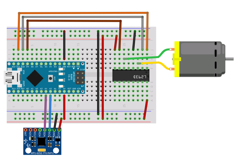
The code attempts to alter the speed of the motor based on the orientation of the GY521. The problem that I encountered was that always after a few times going from stopped to speed the motor would get hung at max speed and the Arduino/Serial output would freeze. This is a problem others have encountered (see http://forum.arduino.cc/index.php?topic=132493.0 and the comments of the trandi link above) and to my knowledge no one has solved.

The toy is a variation on a mobile inverted pendulum (see https://trandi.wordpress.com/2014/01/05/self-balancing-robot/ for inspiration).
The parts list seems to be ever expanding but for now I've got an Arduino Nano (sometimes I use an Uno as well), a 7805 Power Supply, an L293D H bridge IC, a GY 521 gyro/accelerometer combo and a 1.5-3 volt DC motor I got from RadioShack (http://www.radioshack.com/1-5-3vdc-metal-gear-motor/2730258.html), along with typical prototyping essentials (wires, resistors, capacitors, diodes, transistors and a breadboard). I also grabbed the power supply from my playstation 2 (8.5V, 5amp DC) and another from an old modem and have been using them as the power source(s) when not powering from USB.
As preparatory work I soldered wires onto the motor and a male pin header onto the GY 521.
For first effort I wired things up as below, powering the Nano through USB and everything else off the +5V pin on the Nano.
The circuit above is a revised circuit based on comments on the trandi link, adding a separate 7805 power supply fed from the 8.5V Playstation AC adapter, a 5V AC adapter for the motor and powering the Arduino from USB still. This circuit could hardly be more electrically isolated but still the motor locks up at max speed and the Arduino freezes.
This post has languished as a draft for a long time, so I will post now and add more as subsequent parts when I get back to it.
Arduino Pro Mini Clones Part 1
This post is to document my foibles learning to use Arduino Pro Mini Clones.
When I decided it was time to get away from the larger Arduino boards I started shopping for Pro Mini clones, since they can be had pretty cheaply, and can be fit into just about any application. I discovered multiple different PCB designs and decided to buy one of each of the 3 most common unofficial designs to see if I could identify any difference. In all cases these are 5V 16Mhz boards, as I wanted as close a match to my experience with Arduinos Uno and Nano as possible.
Below is a summary of common Arduino Pro Mini (and clones) PCB designs:
Official designs (I didn't purchase either of these, so please take this with a proverbial grain of salt):
-Old Sparkfun Design: (https://www.sparkfun.com/products/retired/9218) sometimes these are sold a bit cheaper than the rest listed below. If someone has a project that they want to put into large scale production, and the project doesn't happen to use the A6 and A7 pins that are not broken out on this board, I suppose the small savings in cost would add up?
-Current Sparkfun Design: (https://www.sparkfun.com/products/11113) this one breaks out the A6 and A7 pins. Exact copies of this design are popular on Ebay.
Unofficial designs (these are the three designs I purchased):
-Common design: This seems to be the most common unofficial design, so for brevity I refer to it as the 'common' design for pro mini clones. It looks like a modification of the old Sparkfun design, but tweaked to have a smaller reset button, making room for three pins (A6, A7 and one additional ground pin) that weren't broken out in the retired Sparkfun board.

-Two Row design: I will refer to this as the 'two row' design, as it can be recognized by the two five-pin rows (or seven? When I say five I am not counting the pins that are part of the long-edge rows of 12 pins each) along the button side edge for a total of 40 pins broken out. The one I bought has those pins marked as shown. I don't know what MIS, MO9, and SCK pins are but if they look like something you need, buy boards of this design, I guess?


-Big Oscillator design: I refer to this as the 'big oscillator' design as it is recognizable by the large oscillator and smaller microcontroller chip on the board. It has 34 pins. Before the boards arrived I looked at this and thought it was the stupidest looking board with the giant oscillator, but the black board and blue LED actually make me like it best aesthetically, now that I've used it a bit. I did see boards with the Big Oscillator design on blue PCB, if anyone cares.

Besides those listed above I saw a few variations on those listed above: A Big Oscillator design but with the larger microcontroller chip and one extra pin broken out (five pins along the button side edge, rather than four, the extra pin assumed to be another ground) and a Common design with four pins next to the button rather than 3, the extra pin apparently one more VCC, but I didn't bother purchasing either.
The only conclusion I can draw about the different designs is to consider your project needs for the pins that are or are not broken out on the board. All boards loaded up fine once I figured out the timing for resetting and got the drivers installed for the different USB to serial converters I was using (the subject of Part 2).
Subscribe to:
Comments (Atom)