Monday, February 3, 2025

The Problem With delay()

     An issue that comes up over and over on Arduino forums supporting Arduinists trying to advance from beginner projects to building their own projects from what they have learned doing tutorials is the problem with delay(). The delay() function is introduced in blink, which is often the first lesson in beginner tutorials.  While the first lesson should be kept simple to keep from immediately confusing the audience, discussion of limitations of delay() are skipped for the same reason. This can lead to an intermediate micro-controller hobbyist attempting to perform some timing function in their project using delay, without ever digesting blink without delay (see also Multitasking the Arduino), leading to difficulties.

    The delay() function might as well be called do_nothing(), as when the controller reaches this instruction, it takes no further action until the specified time has elapsed. The behavior is referred to as 'blocking,' and is at the heart of the problem with delay(). The problem with delay() is that blocking behavior prevents code from being able to perform multiple tasks concurrently. 

 The following sketch illustrates the problem with delay in multiple ways.

/*
This sketch is original work by the author of westwoodtoys.blogspot.com
Permission is hereby granted, free of charge, to any person obtaining a copy
of this software and associated documentation files.
The above copyright notice and this permission notice shall be included in all
copies or substantial portions of the Software.
*/
int leds[]={3,5,6,9,10,11};
int wait_time;
int speakerPin = 4;

void setup()
{
for(int i=0;i<6;i++)
{
pinMode(leds[i],OUTPUT);
}
pinMode(A0,INPUT);
pinMode(2,INPUT);
pinMode(speakerPin,OUTPUT);
}

void play_sounds()
{
for (int n=554; n>522; n--)
{
tone(speakerPin, n);
delay(3);
}
tone(speakerPin, 523);
delay(500);
noTone(speakerPin);
delay(500);
for (int n=554; n>522; n--)
{
tone(speakerPin, n);
delay(3);
}
tone(speakerPin, 523);
delay(1500);
noTone(speakerPin);
}

void loop()
{
for(int i=0;i<6;i++)
{
wait_time=5*analogRead(A0);
digitalWrite(leds[i],HIGH);
delay(wait_time);
digitalWrite(leds[i],LOW);
if(digitalRead(2))
play_sounds();
}
}

Here is a Tinkercad simulation.

The sketch takes input from a potentiometer wiper and button.  The potentiometer wiper position is used to set the time between switching from one LED illuminated to the next. The button causes the Arduino to play a tone on the buzzer that sounds a bit like a fire truck horn.  The problem with delay() is illustrated in that: 

  1. While the horn sound plays, the change in LEDs is paused.
  2. If the potentiometer is moved while one LED is illuminated, the change in duration for the LEDs to be illuminated is not updated until the call to delay() after illuminating the present LED is completed. That is, it would be nice if when the potentiometer is turned to a high resistance, a change in which LED is illuminated could be triggered immedately upon turning the knob to a position matching the current duration the LED has been illuminated rather than having to wait until the duration commanded at time of illumination is completed. 
  3. The button only triggers the horn sound in the period between one LED turning off and the next illuminating.
Of these problems, only #1 is much of a problem while the duration the LEDs are illuminated is small, but #s 2 &3 become more pronounced when the potentiometer wiper commands a longer delay() period. 

The following sketch dodges the problem with delay() by using the lessons learned from 'blink without delay' and Multitasking the Arduino.

/*
This sketch is original work by the author of westwoodtoys.blogspot.com
Permission is hereby granted, free of charge, to any person obtaining a copy
of this software and associated documentation files.
The above copyright notice and this permission notice shall be included in all
copies or substantial portions of the Software.
*/
int leds[]={3,5,6,9,10,11};
int wait_time = 5*1028;
int speakerPin = 4;

//timers added to replace delay function calls
unsigned long this_loop_time;
unsigned long leds_timer;
unsigned long buzzer_timer;

//New variable to make button into a state machine
bool button_pressed = 0;

//New variables to make the buzzer into a state machine
//(keep track of what stage of the sound effect is needed)
int buzzer_counter = 0;
//(keep track of the tone, this replaces 'n' in the for-loop
//in the play_sounds() function the version using delay())
int buzzer_tone=554;
//make array of buzzer durations
int buzzer_duration[]={3,500,500,3,1500};

//new variable to keep track of LED to illuminate
//(this is replacing the for-loop increment 'i')
int leds_counter = 0;

void setup()
{
for(int i=0;i<6;i++)
{
pinMode(leds[i],OUTPUT);
}
pinMode(A0,INPUT);
pinMode(2,INPUT);
pinMode(speakerPin,OUTPUT);
//set the timer so that the first LED lights immediately on startup
leds_timer = millis()-wait_time;
}

void loop()
{
this_loop_time=millis();
wait_time=5*analogRead(A0);
if(this_loop_time-leds_timer>wait_time)
{
//this implementation of digitalWrite() is a little tricky:
//The modulo operator acts like if/else to turn LEDs on
//or off, using not to get the opposite value.
//The counter goes to 12, twice the number of LEDs
//and integer division is leveraged to write to the correct
//LED for even and subsequent odd counter values
digitalWrite(leds[leds_counter/2],!(leds_counter%2));
if(leds_counter%2==0)
//only resetting the timer when lights go on, otherwise
//would have equal duration of off time
leds_timer=this_loop_time;
//increment and reset counter when >=12
leds_counter=(leds_counter+1)%12;
}
if(digitalRead(2)&&button_pressed==0)
{
//the buttton_pressed state variable serves to debounce
//and keep from registering multiple button presses,
//which would interrupt the sound playing
button_pressed=1;
buzzer_timer=this_loop_time;
}
//coding the truck horn sound requires a timer, a counter
//and an array of tone durations. Writing this code is
//quite a bit more involved than the sequential approach
//used in the version using delay()
if(button_pressed)
{
switch(buzzer_counter)
{
case 0:
{
tone(speakerPin, buzzer_tone);
if(this_loop_time-buzzer_timer>buzzer_duration[buzzer_counter])
{
buzzer_tone--;
buzzer_timer=this_loop_time;
}
if(buzzer_tone==523)
buzzer_counter++;
break;
}
case 1:
{
tone(speakerPin, buzzer_tone);
if(this_loop_time-buzzer_timer>buzzer_duration[buzzer_counter])
{
buzzer_counter++;
buzzer_timer=this_loop_time;
}
break;
}
case 2:
{
noTone(speakerPin);
buzzer_tone=554;
if(this_loop_time-buzzer_timer>buzzer_duration[buzzer_counter])
{
buzzer_counter++;
buzzer_timer=this_loop_time;
}
break;
}
case 3:
{
tone(speakerPin, buzzer_tone);
if(this_loop_time-buzzer_timer>buzzer_duration[buzzer_counter])
{
buzzer_tone--;
buzzer_timer=this_loop_time;
}
if(buzzer_tone==523)
buzzer_counter++;
break;
}
case 4:
{
tone(speakerPin, buzzer_tone);
if(this_loop_time-buzzer_timer>buzzer_duration[buzzer_counter])
{
buzzer_counter++;
noTone(speakerPin);
}
break;
}
default:
{
buzzer_counter=0;
buzzer_tone=554;
button_pressed=0;
}
}
}
}

Here is a Tinkercad simulation of this one.

It is probably immediately obvious that this sketch is much longer than the one using delay.  Unfortunately, dodging the problem with delay() is done at cost of increased complexity.  However, when running this sketch, one would see that the three problems are now entirely resolved.  That is:

  1. LED illumination continues to change while playing the horn sound
  2. Changes in potentiometer wiper position are updated immediately
  3. The button will trigger the horn sound upon being depressed, irrespective of the state of the LEDs.
There are a few things to recognize in the difference between the two sketches.  For one, the function controlling the horn sound has been moved into the main loop. This isn't strictly necessary, but makes for easier coding. For another thing, the timing of the LEDs changing does appear to be affected somewhat by the playing of the horn sound.  This is likely because of the increase in loop time when processing the horn sound.  When not playing, a big 'if' condition is bypassed. Finally, if a reader is not familiar with state machines, then surely this code will be hard to parse.

The neophyte will find use of the modulo operator valuable in making state machines work, as demonstrated repeatedly in the code above. If the function of state machines is tricky for the reader, a suggestion for an example project to get a better understanding is to add a counter to 'blink without delay' similar to the use of leds_counter in the sketch above.  It could be used to make the LED blink a variable number of times between a single longer off interval. I call this "for looping without for looping", and this is a fairly crucial concept to understand when moving beyond beginner level micro-controller projects.  

Getting ESP-32 CAM with USB-C SD card to work

     Make this part 2 of a series, I suppose.  The high quality documentation of this device on the seller website marks 4 pins for use in the 'TF' column. TF stands for Trans-Flash, and apparently is a lesser used term for SD card. The savvy SD card user may note that no function is denoted for any of the 4 pins in the 'TF' column.


    A little searching finds that SPI pins can be reassigned.  The following snippet is from the SD card test example:

...

/* Uncomment and setup pins you want to use for the SPI communication #define REASSIGN_PINS int sck = -1; int miso = -1; int mosi = -1; int cs = -1; */

...

#ifdef REASSIGN_PINS SPI.begin(sck, miso, mosi, cs); if (!SD.begin(cs)) { #else if (!SD.begin()) {

    Sometimes brute force is the easiest way, and an approach can be made when realizing that there are only 4! = 24 possible combinations, then trying them one at a time. 

    Surely a programmatic approach could attempt to mount the card with each combination; this exercise is left to the reader.  I preferred just hand jamming one combination, compiling, checking if the card mount failed, and then moving to the next combination. But, failure upon trying the last combination brought me back to the seller provided documentation. The zip file provided by the seller contained a very slightly different pin mapping.

    While still leaving a little ambiguity, I guessed 'CLK' denotes clock (sck) and 'CMD' chip select (cs), just leaving the meanings of 'DAT0' and 'DAT3' to be identified.  I will stop holding dear readers in suspense and just reveal the working pin assignment.  

...
#define REASSIGN_PINS
int sck = 4;
int miso = 13;
int mosi = 21;
int cs = 19;
...
(Looks like it took only 4 tries into hand jamming before I got mixed up, skipping over the working pin mapping, whoops!)

***An update after first publication, it seems that the assumption that CMD maps to cs is NOT correct in the wider world of SD card SPI pin mappings.  Regardless, the pinout reported above does succeed in mounting the SD card and performing the read/write operations of the SD_test example, so maybe the documentation is wrong and I got lucky?

Sunday, February 2, 2025

Getting ESP32 CAM with USB-C Camera to work

    I picked up a different version of ESP32-CAM off Aliexpress.  It purports to support OV-5640 AF, a better camera than the typical ESP32-CAM, and supporting autofocus feature.


    The board has support level about as you would expect from Aliexpress sellers: there are some figures on the product write-up, the seller did send a couple zip files when asked for documentation, and the provided Arduino sketches do not work as written.  The camera fails to initialized, as the pin mapping is not correct.

    Thankfully, the provided documentation does include a schematic for the camera module, and a pin mapping between the camera module and the ESP32.


    Probably the most perplexing move was to provide a figure showing which of the pre-defined cameras to select in the CameraWebServer example sketch, then another image with the pins definitions of that camera overwritten. Thankfully the pin mappings overwritten in the figure are the correct mappings per the previous two figures, but the thought process there is a bit hard to grasp.

The left is the pin definitions in camera_pins.h that comes with the CameraWebServer example. The right is the figure on the seller web page.

    I went ahead and made a new camera definition instead, rather than overwriting the existing definition.  The seller description figures also had some input on how to configure the board.  These do seem necessary, as compile was crapping out without these changes.  


    Finally I tried uploading and met with success.  With corrected pin mapping this board works like any other ESP32 CAM board running the CameraWebServer example.  I guess autofocus works, I don't really remember having a problem with that with the older boards, but surely it is nice to have.

    Will this be the board to make ESP32-CAM a useful product?  Hard to say; it still seems you get what you pay for, and paying a little more gives a little improvement.


Saturday, November 9, 2024

The Pole Vaulter

    I aim to make some blog posts and accompanying videos to present some intermediate level concepts for micro-controller hobbyists.

    There are lots of resources online for beginners.  I learned starting with the Adafruit Arduino Lessons and I have heard good things about the Paul McWhorter Youtube series, to name a few. The Arduino forum, Stack Exchange and Reddit forums are good resources for asking questions.  However, I see some questions come up over and over, so I hope to help address them.

    I've adopted a philosophy toward the projects I am presenting because of one problem in particular that I see on the Arduino Reddit, the Pole Vaulter. The Pole Vaulter has gotten it into their head that 1. a thing called Arduino exists and 2. it can't be that hard.  Armed with this knowledge and unwarranted confidence, the Pole Vaulter grabs their pole (i.e. someone else's project that has been posted online), attempts to vault (recreate that project) and is quickly confronted with their own inadequacies ("Why doesn't it work?!?").

As a reasonable person would not expect to grab a pole and succeed at pole vaulting on their first try, a novice should not attempt to build someone else's project without first learning the fundamentals.

    Because pole vaulters exist, I have specifically made projects that illustrate the lesson of the day but that are not useful for any practical purpose.  My aim is that a pole vaulter might look at what is presented in these projects and find them boring, just a bit of blinking lights and turning knobs.  This would hopefully spare me from having to lecture them on the importance of a solid foundation.  

    By contrast, the Arduinist that has taken time to work through the beginner lessons, hopefully would have, at some point, realized that if they can light a light they can do a little code swapping and make a motor move, turn on a camera, send a bit of data to a database or whatever, and if they can trigger those actions from a potentiometer then the same sort of code swapping can be done with a load cell, a PIR sensor, button input or whatever else.  That is, these lessons use LEDs as generic actuators and Potentiometer wiper position as generic sensors. They exist to make a point, and it is on the intermediate micro-controller hobbyist to take example code and put them together to make something for the pole vaulter to spectacularly fail at reproducing.

Thursday, May 4, 2023

ESP NOW Bidirectional data passage between ESP 8266 and ESP 32


The Random Nerd Tutorials tutorials (here and here) for bidirectional communications using ESP NOW have a bit of unnecessary added complexity, in adding humidity sensors, and in the case of ESP32 a OLED screen.  This post presents pared down sketches demonstrating bidirectional data exchange between an ESP 8266 and ESP32.  These are the same development boards used on the previous ESP NOW post, where each processor is installed on a NODEMCU type breakout board.

As in the previous post, I got the MAC address of each device using the sketch provided on the Random Nerd Tutorial links above.  

These MAC addresses are needed for each board to know where to send messages.  Besides this, the Random Nerd Tutorial sketches were changed to replace the humidity sensors with a potentiometer (and remove the screen).  This allows simplification of the data structure, and I added a little logic to trigger a couple LEDs based on the potentiometer position.  This way I don't need to be connected to serial monitor to know that the sketch is working.

Each board takes input from the wiper of their respective potentiometer and the data read is sent to the other board using ESP NOW.  Two LEDs are connected to each board, one for the local pot and one for that connected to the other board.  

ESP 8266 wiring is as follows:

  • 3.3 V -> Pot high side (red wire)
  • GND -> Pot low side (black wire)
  • A0 -> Pot wiper (yellow wire)
  • D6(GPIO12) -> Green LED anode (green wire)
  • Green LED Cathode -> 150 Ohm Resistor -> GND
  • D7(GPIO13) -> Red LED Anode (white wire)
  • Red LED Cathode -> 150 Ohm Resistor -> GND
ESP 32 wiring is similar:

  • 3.3 V -> Pot high side (red wire)
  • GND -> Pot low side (black wire)
  • G34(GPIO 34) -> Pot wiper (yellow wire)
  • G16(GPIO16) -> Green LED anode (green wire)
  • Green LED Cathode -> 150 Ohm Resistor -> GND 
  • G17(GPIO17) -> Red LED Anode (white wire)
  • Red LED Cathode -> 150 Ohm Resistor -> GND 

The LEDs illuminate if the pot wiper is past the halfway point.  Below is when the ESP 32 pot is turned up:


... and when the ESP 8266 wiper is turned up:


Maybe I will make a video later, as the images aren't terribly exciting.

Below is the ESP 8266 sketch:

/*
  This sketch is rework of a sketch first written by Rui Santos and presented on:
  https://RandomNerdTutorials.com/esp-now-two-way-communication-esp8266-nodemcu/
  
  Permission is hereby granted, free of charge, to any person obtaining a copy
  of this software and associated documentation files.
  
  The above copyright notice and this permission notice shall be included in all
  copies or substantial portions of the Software.
*/

#include <esp8266wifi.h>
#include <espnow.h>


// REPLACE WITH THE MAC Address of your receiver 
uint8_t broadcastAddress[] = {0x58, 0xBF, 0x25, 0x31, 0x9D, 0xE0};

int arriving_data=0;
int local_data=0;
const long interval = 200; 
unsigned long previousMillis = 0;

//Structure example to send data
//Must match the receiver structure
typedef struct struct_message {
    int reading;
} struct_message;

// Create a struct_message to hold sensor readings
struct_message outbound;

// Create a struct_message to hold incoming sensor readings
struct_message inbound;

// Callback when data is sent
void OnDataSent(uint8_t *mac_addr, uint8_t sendStatus) {
  Serial.print("Last Packet Send Status: ");
  if (sendStatus == 0){
    Serial.println("Delivery success");
  }
  else{
    Serial.println("Delivery fail");
  }
}

// Callback when data is received
void OnDataRecv(uint8_t * mac, uint8_t *incomingData, uint8_t len) {
  memcpy(&inbound, incomingData, sizeof(inbound));
  Serial.print("Bytes received: ");
  Serial.println(len);
  arriving_data = inbound.reading;
}

void read_pot(){
  local_data = analogRead(A0);
  Serial.print("Pot reading: ");
  Serial.println(local_data);
}

void printIncomingReadings(){
  // Display Readings in Serial Monitor
  Serial.println("INCOMING READINGS");
  Serial.println(arriving_data);
}
 
void setup() {
  // Init Serial Monitor
  Serial.begin(115200);
  pinMode(12,OUTPUT);
  pinMode(13,OUTPUT);
  // Set device as a Wi-Fi Station
  WiFi.mode(WIFI_STA);
  WiFi.disconnect();

  // Init ESP-NOW
  if (esp_now_init() != 0) {
    Serial.println("Error initializing ESP-NOW");
    return;
  }

  // Set ESP-NOW Role
  esp_now_set_self_role(ESP_NOW_ROLE_COMBO);

  // Once ESPNow is successfully Init, we will register for Send CB to
  // get the status of Trasnmitted packet
  esp_now_register_send_cb(OnDataSent);
  
  // Register peer
  esp_now_add_peer(broadcastAddress, ESP_NOW_ROLE_COMBO, 1, NULL, 0);
  
  // Register for a callback function that will be called when data is received
  esp_now_register_recv_cb(OnDataRecv);
}
 
void loop() {
  unsigned long currentMillis = millis();
  if (currentMillis - previousMillis >= interval) {
    // save the last time you updated the DHT values
    previousMillis = currentMillis;

    //Get pot readings
    read_pot();

    //Set values to send
    outbound.reading = local_data;

    // Send message via ESP-NOW
    esp_now_send(broadcastAddress, (uint8_t *) &outbound, sizeof(outbound));

    // Print incoming readings
    printIncomingReadings();
    
  }
  if(arriving_data>2048)
  {
  digitalWrite(12, HIGH);
  } 
  else
  {
    digitalWrite(12, LOW);
  }
  if(local_data>512)
  {
    //Serial.println("writing local led high");
    digitalWrite(13, HIGH);
  }
  else
  {
    //Serial.println("writing local led low");
    digitalWrite(13, LOW);
  }
}
...and the ESP32 sketch:
/*
  This sketch is rework of a sketch first written by Rui Santos and presented on:
  https://RandomNerdTutorials.com/esp-now-two-way-communication-esp32/
  
  Permission is hereby granted, free of charge, to any person obtaining a copy
  of this software and associated documentation files.
  
  The above copyright notice and this permission notice shall be included in all
  copies or substantial portions of the Software.
*/

#include <esp_now.h>
#include <wifi.h>

// REPLACE WITH THE MAC Address of your receiver 
uint8_t broadcastAddress[] = {0xBC, 0xFF, 0x4D, 0x4A, 0x4D, 0x6A};

int arriving_data=0;
int local_data=0;
const long interval = 200; 
unsigned long previousMillis = 0;

//Structure example to send data
//Must match the receiver structure
typedef struct struct_message {
    int reading;
} struct_message;

// Create a struct_message to hold sensor readings
struct_message outbound;

// Create a struct_message to hold incoming sensor readings
struct_message inbound;

esp_now_peer_info_t peerInfo;

// Callback when data is sent
void OnDataSent(const uint8_t *mac_addr, esp_now_send_status_t status) {
  Serial.print("\r\nLast Packet Send Status:\t");
  Serial.println(status == ESP_NOW_SEND_SUCCESS ? "Delivery Success" : "Delivery Fail");
}

// Callback when data is received
void OnDataRecv(const uint8_t * mac, const uint8_t *incomingData, int len) {
  memcpy(&inbound, incomingData, sizeof(inbound));
  Serial.print("Bytes received: ");
  Serial.println(len);
  arriving_data = inbound.reading;
}

void read_pot(){
  local_data = analogRead(34);
  Serial.print("Pot reading: ");
  Serial.println(local_data);
}

void printIncomingReadings(){
  // Display Readings in Serial Monitor
  Serial.println("INCOMING READINGS");
  Serial.println(arriving_data);
}
 
void setup() {
  // Init Serial Monitor
  Serial.begin(115200);
  pinMode(16,OUTPUT);
  pinMode(17,OUTPUT);
 
  // Set device as a Wi-Fi Station
  WiFi.mode(WIFI_STA);

  // Init ESP-NOW
  if (esp_now_init() != ESP_OK) {
    Serial.println("Error initializing ESP-NOW");
    return;
  }

  // Once ESPNow is successfully Init, we will register for Send CB to
  // get the status of Trasnmitted packet
  esp_now_register_send_cb(OnDataSent);
  
  // Register peer
  memcpy(peerInfo.peer_addr, broadcastAddress, 6);
  peerInfo.channel = 0;  
  peerInfo.encrypt = false;
  
  // Add peer        
  if (esp_now_add_peer(&peerInfo) != ESP_OK){
    Serial.println("Failed to add peer");
    return;
  }
  // Register for a callback function that will be called when data is received
  esp_now_register_recv_cb(OnDataRecv);
}
 
void loop() {
  unsigned long currentMillis = millis();
  if (currentMillis - previousMillis >= interval) 
  {
    previousMillis = currentMillis;
    
  read_pot();
 
  // Set values to send
    outbound.reading = local_data;

  // Send message via ESP-NOW
  esp_err_t result = esp_now_send(broadcastAddress, (uint8_t *) &outbound, sizeof(outbound));
   
  if (result == ESP_OK) {
    Serial.println("Sent with success");
  }
  else {
    Serial.println("Error sending the data");
  }

  }
    if(arriving_data>512)
  {
  digitalWrite(16, HIGH);
  } 
  else
  {
    digitalWrite(16, LOW);
  }
  if(local_data>2048)
  {
    //Serial.println("writing local led high");
    digitalWrite(17, HIGH);
  }
  else
  {
    //Serial.println("writing local led low");
    digitalWrite(17, LOW);
  }
}

Surely this circuit could be made even simpler.  As a learning exercise, the novice may consider replacing the potentiometer with a switch and  taking a digital reading rather than powering the local LED by GPIO.

Sunday, December 18, 2022

ESP NOW sender and receiver basic project

ESP Now seems to be a link layer protocol for the ESP 32 and ESP 8266.  It is easy to use for a simple project passing data between an ESP 8266 with a sensor attached, to an ESP 32 with an actuator.

randomnerdtutorials.com has example ESP NOW code for the ESP8266 and ESP32, which form the basis for this project.

The addressing of ESP NOW uses MAC addresses.  In this project, the ESP 8266 is sending data to the ESP 32.  So, the MAC address of the ESP 32 is needed.  There is a code snippet in the link above that can be loaded into the ESP 32, and the MAC address retrieved from Arduino Serial Monitor.  In my case this address was 58:BF:25:31:9D:E0


This was put into the example code from the link above, for the ESP 8266:
/*
  Original Code by Rui Santos, edited for illustration of sensor data forwarding via ESP NOW on ESP 8266
  Complete project details at https://RandomNerdTutorials.com/esp-now-esp8266-nodemcu-arduino-ide/
  
  Permission is hereby granted, free of charge, to any person obtaining a copy
  of this software and associated documentation files.
  
  The above copyright notice and this permission notice shall be included in all
  copies or substantial portions of the Software.
*/

#include <ESP8266WiFi.h>
#include <espnow.h>

// REPLACE WITH RECEIVER MAC Address
uint8_t broadcastAddress[] = {0x58, 0xBF, 0x25, 0x31, 0x9D, 0xE0};

// Structure example to send data
// Must match the receiver structure
typedef struct struct_message {
  char a[32];
  int b;
  float c;
  String d;
  bool e;
} struct_message;

// Create a struct_message called myData
struct_message myData;

unsigned long lastTime = 0;  
unsigned long timerDelay = 250;  // send readings timer

// Callback when data is sent
void OnDataSent(uint8_t *mac_addr, uint8_t sendStatus) {
  Serial.print("Last Packet Send Status: ");
  if (sendStatus == 0){
    Serial.println("Delivery success");
  }
  else{
    Serial.println("Delivery fail");
  }
}
 
void setup() {
  // Init Serial Monitor
  Serial.begin(115200);
 
  // Set device as a Wi-Fi Station
  WiFi.mode(WIFI_STA);

  // Init ESP-NOW
  if (esp_now_init() != 0) {
    Serial.println("Error initializing ESP-NOW");
    return;
  }

  // Once ESPNow is successfully Init, we will register for Send CB to
  // get the status of Trasnmitted packet
  esp_now_set_self_role(ESP_NOW_ROLE_CONTROLLER);
  esp_now_register_send_cb(OnDataSent);
  
  // Register peer
  esp_now_add_peer(broadcastAddress, ESP_NOW_ROLE_SLAVE, 1, NULL, 0);
}
 
void loop() {
  if ((millis() - lastTime) > timerDelay) {
    // Set values to send
    strcpy(myData.a, "THIS IS A CHAR");
    myData.b = analogRead(A0);
    myData.c = 1.2;
    myData.d = "Hello";
    myData.e = false;

    // Send message via ESP-NOW
    esp_now_send(broadcastAddress, (uint8_t *) &myData, sizeof(myData));

    lastTime = millis();
  }
}
The only changes made to the original code are inputting the MAC address of the ESP 32, changing the value of the 'timerDelay' variable, and changing assignment to mydata.b from 'random(1,20);' to 'analogRead(A0);'.  The wiring is as follows:
  • ESP8266 3.3 V Pin to Potentiometer High
  • ESP8266 Gnd Pin to Potentiometer Low
  • ESP8266 A0 Pin to Potentiometer wiper
Once flashed, the ESP8266 is powered by a 5V lithium battery, intended for use as a cellphone battery charger.

The ESP 32 code from the link above also has minor changes:
/*
  Original code by Rui Santos, minor additions made to actuate an LED upon receipt of ESP
  NOW data exceeding an arbitrary threshold.
  Complete project details at https://RandomNerdTutorials.com/esp-now-esp32-arduino-ide/
  
  Permission is hereby granted, free of charge, to any person obtaining a copy
  of this software and associated documentation files.
  
  The above copyright notice and this permission notice shall be included in all
  copies or substantial portions of the Software.
*/

#include <esp_now.h>
#include <WiFi.h>

// Structure example to receive data
// Must match the sender structure
typedef struct struct_message {
    char a[32];
    int b;
    float c;
    bool d;
} struct_message;

// Create a struct_message called myData
struct_message myData;

// callback function that will be executed when data is received
void OnDataRecv(const uint8_t * mac, const uint8_t *incomingData, int len) {
  memcpy(&myData, incomingData, sizeof(myData));
  Serial.print("Bytes received: ");
  Serial.println(len);
  Serial.print("Char: ");
  Serial.println(myData.a);
  Serial.print("Int: ");
  Serial.println(myData.b);
  Serial.print("Float: ");
  Serial.println(myData.c);
  Serial.print("Bool: ");
  Serial.println(myData.d);
  Serial.println();
}
 
void setup() {
  // Initialize Serial Monitor
  Serial.begin(115200);
  pinMode(4, OUTPUT);
    digitalWrite(4, HIGH);
    
  // Set device as a Wi-Fi Station
  WiFi.mode(WIFI_STA);

  // Init ESP-NOW
  if (esp_now_init() != ESP_OK) {
    Serial.println("Error initializing ESP-NOW");
    return;
  }
  
  // Once ESPNow is successfully Init, we will register for recv CB to
  // get recv packer info
  esp_now_register_recv_cb(OnDataRecv);
}
 
void loop() {
if(myData.b>512)
{
  digitalWrite(4, HIGH);
  }
  
  else
  {
    digitalWrite(4, LOW);
    }
}
The only changes made to the original code is addition of the 'if' and 'else' statements within the loop, and 'pinMode(4,OUTPUT);' and 'digitalWrite(4,HIGH);' in setup to make pin 4 ready to actuate an LED. The wiring is as follows:
  • ESP32 Pin 4 to LED Anode
  • LED Cathode to 150 Ohm resistor
  • 150 Ohm Resistor to ESP32 Gnd Pin
Once flashed, the ESP 32 is powered by my PC USB port.  I can monitor the data received on Arduino Serial monitor, and confirm that the LED illuminates when the potentiometer wiper passes the 512 position.


Note "Int: 770", the wiper is past the threshold, the LED is on: 


Now the wiper is below the threshold ('Int: 390') and the LED is off:


Paring down the data structure to only send data that is necessary to function is an exercise left to the reader.

Friday, November 11, 2022

Multi-serial with software serial on Arduino Uno, Nano, etc

A problem an Arduino novice may face is the inclination to connect to a serial device (such as a Loadstar Loadcell read by their proprietary serial interface or a Benewake TF-LC02 Lidar Sensor) to an Arduino board with only one hardware serial interface (such as Arduino Uno or Nano) and then open the Arduino IDE Serial Monitor with hopes of using it to communicate with the serial device. This novice would (hopefully) notice right away that things aren't going as hoped. 

This post explains why this doesn't work.  My own experience is that I could send to the device but not get anything back, which is a little different that what is posted in that link, though I make no claim to knowing why.

The best solution allowing connection of Serial Monitor for input/output to a serial device, in my opinion, is to use an Arduino board with multiple hardware serial interfaces, such as an Arduino MEGA2560. The sample code here allows connection of a serial device to a second serial interface, relays all input and output to the Serial Monitor and vice versa.  This allows for testing of commands to the device, and a more involved sketch can be built out from there.

Unfortunately, the notional novice may be disinclined to buy new hardware.  Arduino does have at least one library for implementing a serial interface via software.  The code below adapts the code from the link above for use with boards with only one hardware serial interface, by using the Arduino Software Serial Library.  

The code:
  /*
  Multiple serial test with software serial

  Receives from the main serial (Serial 0), sends to software serial port configured in the code.
  Receives from software serial port, sends to the main serial port.

  This example works with boards with only one serial like Arduino Uno, Nano etc.

  The circuit:
  - any serial device attached to software serial pins defined below
    -device tx connects to Arduino pin 2
    -device rx connects to Arduino pin 3
    -device GND connects to Arduino GND
    -use own discretion about powering device (Device Vcc to 5v Arduino pin if safe)

  - Serial Monitor open on Serial port 0

  Adapted 10 Nov 2022 from Arduino multi serial code found at:
  https://docs.arduino.cc/built-in-examples/communication/MultiSerialMega.

  Original code:
  created 30 Dec 2008
  modified 20 May 2012
  by Tom Igoe & Jed Roach
  modified 27 Nov 2015
  by Arturo Guadalupi

  This example code is in the public domain.
*/


#include <SoftwareSerial.h>
const byte SSrx = 2;
const byte SStx = 3;

SoftwareSerial SoftSerial (SSrx, SStx);

void setup() {
  // initialize both serial ports:
  Serial.begin(115200);
  pinMode(SSrx, INPUT);
  pinMode(SStx, OUTPUT);
  SoftSerial.begin(115200);
}

void loop() {
  // read from software serial, send to built in serial:
  if (SoftSerial.available()) {
    int inByte = SoftSerial.read();
    Serial.write(inByte);
  }

  // read from built in serial, send to software serial:
  if (Serial.available()) {
    int inByte = Serial.read();
    SoftSerial.write(inByte);
  }
}
My experience is that the software serial connection generally works OK, but can't be relied upon 100% of the time.  Some bytes (or whole strings of bytes) may come through as the wrong characters, which is why I suggested the better solution is to use a board with more than one hardware serial connection.

Still, the sketch above may meet the novice's needs for demonstrating the serial connection and testing out a few commands.  Wiring should be as follows:
  • Device TX to Arduino pin 2
  • Device RX to Arduino pin 3
  • Device GND to Arduino GND pin
If the device accepts 5V and current draw is within the limits of what can be supplied by the Arduino board, and powering from the Arduino is desired, then also connect
  • Device Vcc to Arduino 5V pin
Below shows an Arduino Uno running the sketch above connected to an Arduino MEGA2560 (clone) using multi serial.

Output is shown in the screen capture below.  


As can be seen, the Arduino Uno seems to send just fine, but its receiving leaves something to be desired.

Thursday, June 23, 2016

The barest fundementals

This post is written to be a pre-introduction to Arduino for an absolute novice (i.e. someone without a background in computer science, engineering, or calculus based physics).  We will discus the simplest electrical concepts that will be expanded upon as future lessons progress.

The water in pipes analogy

Imagine a water tower with a water wheel at the base, piping between the tank and the water wheel, and a valve to allow or stop flow.

Let's start by saying the valve is closed.

In physics, the water in the tower is said to possess 'potential energy.'  The water isn't doing anything; it is just sitting there.  But it is up high, and because of gravity it has the potential to be used below to turn the water wheel.


Now suppose we open the valve.

When the valve is opened, the speed of the water coming down the pipe will depend on the height of the tower and the water level in the tank, as well as whether the valve is fully open or only part way.

The speed of the water flow will influence how fast the water wheel turns, and correspondingly, how much energy can be extracted from it (if, for instance it were connected to a generator, or a device used for grinding grain, or whatever one uses a water wheel for).  

Here we have already touched on the fundamentals necessary to talk about electricity.
  • Voltage is a measure of electrical potential, similar to the height of the water level.
  • Current is a measure of how much electricity is flowing, similar to the rate of water flow through the pipe.
  • Resistance is a measure of how much the wires and electrical components slow down the electrical flow (current) similar to the way the valve passes more or less water based on how open it is.

Circuits


A circuit is a loop.  Outside of the field of electronics, a race car might be said to be completing a circuit as it goes around a loop-shaped track. When talking about electrical systems, the term circuit is used to describe the path the electricity travels on when moving from a location with higher potential (voltage) to one of lower potential, and a simple diagram will show that that path is also a loop.


The circuit diagram above is for a flashlight.  A legend for the icons is bellow. 

Switch


Resistance
Light Bulb
Battery

The lines connecting the icons are the flashlight's wiring. 


Current flows on the wiring out of the positive side of the battery (marked "+"), through the switch (when the switch is closed), and through the light bulb to the negative side of the battery (marked "-").  So altogether it forms a loop or circuit.


Although in the diagram the resistance is marked as a single icon, in real life there is resistance all along the wire, inside the battery, in the switch and in the light bulb.  The resistance is marked as a single icon because it makes analysis of the circuit easier; if you want to know why, ask how in the comments, but it requires a bit of explanation that I didn't intend to get into here.

Bringing it all together

The concept of a circuit diverges from the water in pipes analogy a bit: In the water tower example, the water could just dump out on the ground after hitting the water wheel, and maybe it would run into a river or wherever.  A loop could be formed by having a collecting pool and a pump that charges water back to the tower, perhaps, but that does nothing to illustrate a fundamental difference between water and electricity: If a circuit is not connected by wire or some other current carrying material (light bulb filament, or the material from which the switch is made) the break is equivalent to an opened switch: current won't flow.  In terms of water flowing through pipes, if a pipe is severed, water will blow everywhere until a valve is closed stopping flow into the pipe upstream. 

In physical terms, a disconnected circuit experiences infinite resistance to (electrical current) flow, whereas a severed pipe presents zero resistance to (water) flow.  The implication of this is that when we are working with electricity, for anything to happen the current will need a way in (a path from high potential), and a way out (a path to low potential)


Thursday, June 9, 2016

How to make Retropie work

This post is for visitors to my family's VRBO house.

In the downstairs bedroom I've provided a RetroPie, a Raspberry Pi micro-computer configured to emulate Nintendo Entertainment System and Super Nintendo for playing each respective systems' video games.


The RetroPie is fairly straightforward to use, but these instruction may help if any problems are encountered.
  • Turn on the TV, tuned to video input and plug in the micro USB cable.
    • If nothing happens, unplug and try again, as sometimes it doesn't take on the first power up.
    • When plugged in you can see a couple LEDs shining through the vent on the side.  When it is working right the red will be illuminated, as well as the green; when it isn't working the red will be on but not green.
  • If things are going correctly, a screen with four raspberries will be displayed, followed by some computer script, a 'Retropie' splash screen, a bit more script, an 'Emmulation Station' splash screen, and finally the main interface.
    • On rare occasions a guest may be prompted to configure the controller.  Follow on-screen prompts to configure the buttons.  The 'L' and 'R' shoulder buttons should be configured to the 'bottom L' and 'bottom R' buttons, respectively.  Buttons not found on the controller can be skipped by holding down any button for a few seconds.
  • On the main interface you can use either USB controller to select Nintendo Entertainment System or Super Nintendo by pressing left or right on the controller 'D' pad, and pushing the 'A' button. You will find long lists of games you can try.  
  • If you get tired of one game while playing you can press 'start' and 'select' at the same time to exit from that game.
  • The other options probably won't be of much interest to a casual user, but if you find something you like please leave me a comment, as I haven't spent a lot of time exploring the games and such that come with the default RetroPie distribution.  I think there is Doom and Minecraft, but I haven't spent any time on them.
All Super Nintendo and Nintendo Entertainment System ROMs are legal copies of games from my collection, procured between ~1987-2005.

Fully configured devices are available for purchase on my ebay store (link), but the micro SD card that comes with it will necessarily not contain the game ROMs (we aim to avoid unlawful distribution of those files).   If the micro SD card goes missing during your stay a $20.00 replacement fee will be assessed from the credit card that was used to make the deposit for the house.  If the entire system is removed the replacement fee is $100.00.

Incidentally, this system is capable of playing games from systems as powerful as the original Playstation.  A more powerful version capable of emulating Nintendo 64 titles will be made available when the Raspberry Pi 3 becomes more available.


Wednesday, March 9, 2016

Arduino Pro Mini Clones Part 2

Continuing my investigation of cheap Chinese knock offs of Sparkfun's Arduino Pro Mini design...

As mentioned in Part 1, I purchased one of each of what I called the Common, Two Row and Big Oscillator PCB designs.  Since Part 1 I went ahead and bought the other two common designs as well, the old and new Sparkfun designs.

Of course the first difficulty a novice will find when graduating to using pro mini clones is overcoming the lack of USB port.  Anticipating this I ordered the Two Row board as a package deal that came with three different kinds of USB to Serial converters: PL2303, CH340 and CP2102.

All three converters required drivers, found at the following sites (I was using a Mac, for other OSs you may have search around):

PL2303 - http://www.prolific.com.tw/US/ShowProduct.aspx?p_id=229&pcid=41
CH340 - http://www.wch.cn/downloads.php?name=pro&proid=5
CP2102 - https://www.silabs.com/products/mcu/Pages/USBtoUARTBridgeVCPDrivers.aspx

The wiring between any converter and board should be as follows:
5V to VCC
Ground to Ground
TX to RX
RX to TX

After loading up drivers and figuring out the correct wiring, the next problem I ran into was that all three of these USB converters have no support for automated resetting of the board during programming.  This results in an error while programming almost every time (I can't say why, but on the first try the program went through perfectly without any messing with reset, but later attempts almost always failed).

I started searching for the reason and was pretty disappointed by the level of detail in the answers (basically, answers were along the line of "reset before/during upload").  One suggestion was to turn on verbose output,
which I found helpful at slowing down the upload process, but I still couldn't figure out exactly when to press reset, whether to hold it for a little while or release immediately and so forth.  After a bit of trial and error I did get the timing figured out and I will post a video of the process so that it is perfectly clear how to get a good load.  Hopefully a video can save any intrepid readers that same trial and error, as pushing and releasing the reset button has a certain rhythm to it that works for me.

Once the timing was sorted out, the converters all work fine, and now that the drivers are loaded on my computer I could grab one indiscriminately when I want to load a sketch.

Ultimately, it should be noted that this is a super scrimp-and-save approach that led to extra headaches which an FTDI USB to serial converter would avoid for just a little more money spent, as the FTDI converters support automated resetting during sketch uploading.  After having so much fun figuring out how to use the others I went ahead and purchased an FT232RL FTDI USB to serial converter.  I intend to use it as my go-to programmer, allowing upload without this rhythmic button pushing nonsense.  It didn't need any drivers, though I use a Mac and I think I heard mention of needing drivers for windows.  Good luck finding them.

Finally, I did see some suggestions to solder headers to the 6 pins of the pro mini used in uploading, and while I agree that it is good engineering practice, I don't tend to have the patience for it.  I usually can still get a good load if I hold the header with the wires to the converter in contact with the board just so.  Your mileage may vary; break out the soldering iron if you think you need it.

Wednesday, February 17, 2016

DC motor blues Part 2

Because the circuits shown in Part 1 haven't been worked on for a while, this post is to outline my plan of action for picking the project back up and troubleshooting using a systematic approach.  Part 3 will post results and code snippets.


-Build the circuit as shown in the first picture of Part 1 using most recent save of code to confirm the problem exists as documented (create a baseline).
-Build the circuit and use code from Adafruit Learn Arduino Lesson 15 (https://learn.adafruit.com/adafruit-arduino-lesson-15-dc-motor-reversing/arduino-code) to see if the motor is causing the freeze ups.


-Used the existing code with gyro but LEDs in place of the motor, in parallel with bias in opposite directions; expectation is that one LED will illuminate when tilted one way, the other for the other way.  Check that the serial output never freezes up for the duration.


-Built the circuit from the first picture of Part 1 using different DC motors.  The motor is called 1.5-3V, but it is weak at those voltages.


-Stack L293D chips, in case they are being overloaded.  Connect all grounds, as the ground pins are also described as heat sink in documentation.
-Use Arduino Uno instead of Nano as the micro controller. 
-Build the circuit as shown in the second picture of Part 1 and repeat all previous steps.


This will provide some data on whether the problem can be isolated.  Additional steps are:


-Build circuits as shown in other projects that work online, using their code.  See if the same problem occurs.
-Consider reworking code to allow using a potentiometer to control motor speed as in Lesson 15 while taking readings on the Gyro (attempt to divorce Gyro and motor)

DC motor blues Part 1

This post is to document a problem I'm having getting some electronics (that will drive a toy I'm building) to work.


The toy is a variation on a mobile inverted pendulum (see https://trandi.wordpress.com/2014/01/05/self-balancing-robot/ for inspiration). 


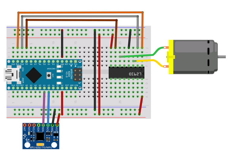
The parts list seems to be ever expanding but for now I've got an Arduino Nano (sometimes I use an Uno as well), a 7805 Power Supply, an L293D H bridge IC,  a GY 521 gyro/accelerometer combo and a 1.5-3 volt DC motor I got from RadioShack (http://www.radioshack.com/1-5-3vdc-metal-gear-motor/2730258.html), along with typical prototyping essentials (wires, resistors, capacitors, diodes, transistors and a breadboard).  I also grabbed the power supply from my playstation 2 (8.5V, 5amp DC) and another from an old modem and have been using them as the power source(s) when not powering from USB.


As preparatory work I soldered wires onto the motor and a male pin header onto the GY 521. 


For first effort I wired things up as below, powering the Nano through USB and everything else off the +5V pin on the Nano.


The code attempts to alter the speed of the motor based on the orientation of the GY521.  The problem that I encountered was that always after a few times going from stopped to speed the motor would get hung at max speed and the Arduino/Serial output would freeze.  This is a problem others have encountered (see http://forum.arduino.cc/index.php?topic=132493.0 and the comments of the trandi link above) and to my knowledge no one has solved.


The circuit above is a revised circuit based on comments on the trandi link, adding a separate 7805 power supply fed from the 8.5V Playstation AC adapter, a 5V AC adapter for the motor and powering the Arduino from USB still.  This circuit could hardly be more electrically isolated but still the motor locks up at max speed and the Arduino freezes.

This post has languished as a draft for a long time, so I will post now and add more as subsequent parts when I get back to it.